InputGeometry
| Type: | section |
|---|---|
| Appearance: | simple |
This section is used to specify a geometric misalignment caused by a deviation of the optical system’s object plane from the user’s input plane to which the Fourier transforms actually refers. The situation is as depicted in Figure “Input geometry”.
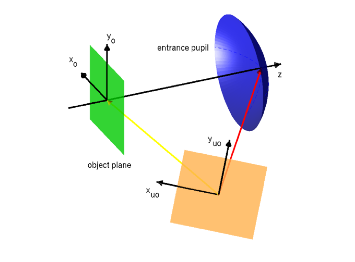
Input geometry
The actual user’s input plane is shown in orange. It is equipped with user input coordinates  . The user input plane is tilted and translated (yellow vector) with respect to the optical system’s object plane. This geometric misalignment causes aberrations, which are taken into account by
 JCMsuite when computing the image. The rotation and translation are set by the parameters Rotation and Center respectively. The red ray from the center of the user’s input plane to the center of the entrance pupil is called chief ray.
Example: A defocus of 50nm of an optical system may be specified as follows:
PostProcess {
  OpticalImaging {
    InputFileName = "fourier_coefficients_in.jcm"
    OutputFileName = "fourier_coefficients_out.jcm"
    OpticalSystem {
      NumericalAperture = 1.35
      SpotMagnification = 0.25
      OutputRefractiveIndex = 1.498
    }
    InputGeometry {
      Center = [0, 0, 50.0e-9]
    }
    OutputGeometry {}
  }
}