Shape Derivatives
Learning targets (advanced)
- Parameterize extrusion geometry for shape derivatives
Often it is of major importance to study the dependency of simulation results for a changing geometry (shape). JCMsuite allows to efficiently compute derivatives of simulation results with respect to geometrical shape parameters. This yields a linear approximation of the output results with respect to shape parameters.
This example parameterize the shape of the cylinder from the previous section. The structure of layout.jcm file is as follows:
Layout3D {
  Extrusion {
    Objects {
      Circle {
        Name = "Circle"
        Radius = 1
        ...
      }
    }
    MultiLayer {
      LayerInterface {
        BoundaryClass = Transparent
      }
      Layer {
        Thickness = 1.0
        DomainId = 1
      }
      LayerInterface {
        Name = "InterfaceBottom"
        GeometryValues = [
          Circle/Radius = 1.0
        ]
        GlobalZ = 0.0
      }
      Layer {
        Name = "CylinderLayer"
        Thickness = 1.5
        ...
      }
      LayerInterface {
        Name = "InterfaceTop"
        GeometryValues = [
          Circle/Radius = 1.0
        ]
      }
      Layer {
        Name = "TopLayer"
        Thickness = 2.0
        DomainIdMapping = [1 2]
      }
      LayerInterface {
        BoundaryClass = Transparent
      }
    }
  }
}
Now, if you want to make the bottom radius, the top radius and the height to become differential shape parameters, declare three derivative parameters at the beginning of the layout.jcm file:
DerivativeParameter {
  Name = "RadiusBottom"
  TreeEntry = Layout3D/Extrusion/MultiLayer/InterfaceBottom/GeometryValues/Circle/Radius
}

DerivativeParameter {
  Name = "RadiusTop"
  TreeEntry = Layout3D/Extrusion/MultiLayer/InterfaceTop/GeometryValues/Circle/Radius
}

DerivativeParameter {
  Name = "Height"
  TreeEntry = Layout3D/Extrusion/MultiLayer/CylinderLayer/Thickness
  TreeEntry {
    Path = Layout3D/Extrusion/MultiLayer/TopLayer/Thickness
    Scaling = -1.0
  }
}
The entries TreeEntry refers to the actual value in the .jcm input tree. TreeEntry has the form of a path name in the .jcm input tree which is just the concatenation of the section tag followed by the final entry tag. For example, when you look at the structure of the layout.jcm file above, the tree path to the thickness parameter of the second layer is Layout3D/Extrusion/MultiLayer/Layer{2}/Thickness. For named sections (e.g. Name="CylinderLayer) you can use the section name instead of its original section tag which makes it more comfortable when adding further layers. Here, we therefore can use the Layout3D/Extrusion/MultiLayer/CylinderLayer/Thickness.
In the last DerivativeParameter section we used two TreeEntry definitions. The first one is the natural variation of the layer thickness of the cylinder. The second one affects the top layer in such a way that the upper  -position of the computational domain is not changed.
Note
As an alternative you may skip the TreePath declaration in the DerivativeParameter section above and define the derivative directly after the value in  brackets, see DerivativeParameter and the modified
 layout_alternative.jcm below.
With shape derivative parameter defined, JCMsolve will also compute the derivatives of the fields and their post process values with respect to the geometrical parameters.
JCMview allows to display the deformed meshes
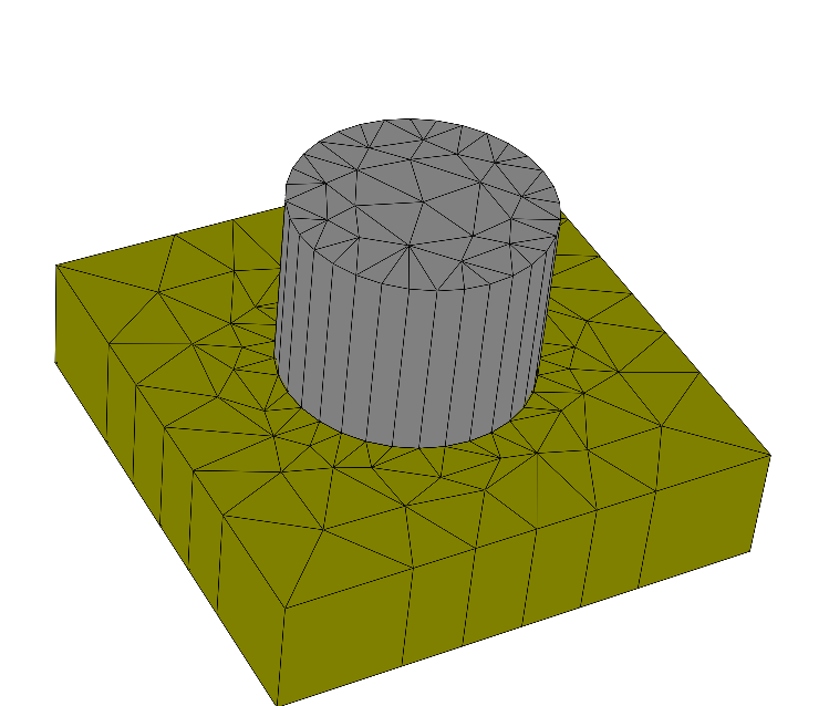
Undisplaced mesh (  ,
,  ,
,  )
)
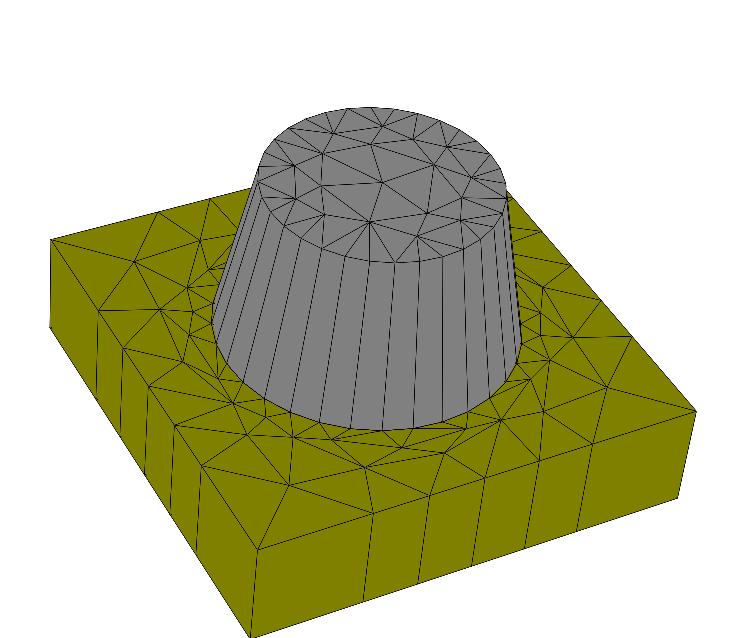
Displaced mesh (  , , )
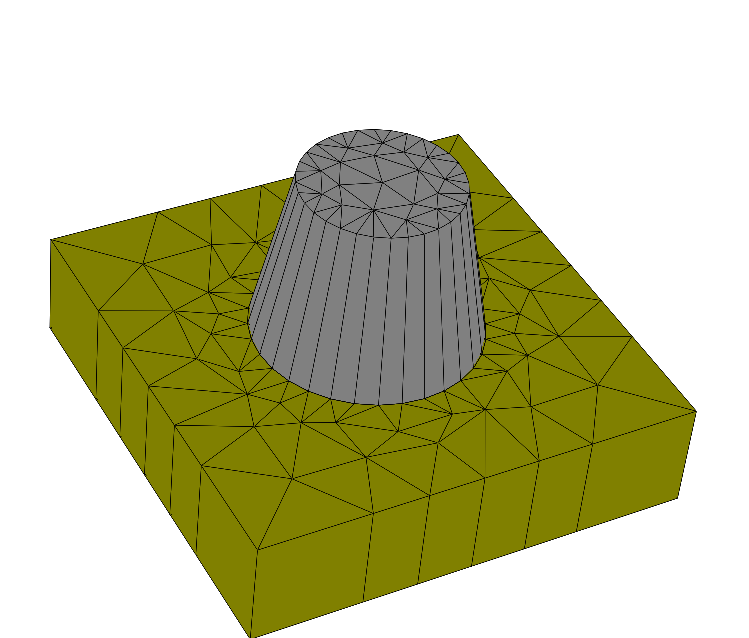
Displaced mesh ( , 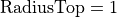 , )
, )
Displaced mesh ( , ,  )
)
.jcm Input File
layout.jcm [ASCII]
 1
 2
 3
 4
 5
 6
 7
 8
 9
10
11
12
13
14
15
16
17
18
19
20
21
22
23
24
25
26
27
28
29
30
31
32
33
34
35
36
37
38
39
40
41
42
43
44
45
46
47
48
49
50
51
52
53
54
55
56
57
58
59
60
61
62
63
64
65
66
67
68
69
70
71
72
73
74
75
76
77
78
79
80
81
82
83
DerivativeParameter {
  Name = "RadiusBottom"
  TreeEntry = Layout3D/Extrusion/MultiLayer/InterfaceBottom/GeometryValues/Circle/Radius
}

DerivativeParameter {
  Name = "RadiusTop"
  TreeEntry = Layout3D/Extrusion/MultiLayer/InterfaceTop/GeometryValues/Circle/Radius
}

DerivativeParameter {
  Name = "Height"
  TreeEntry = Layout3D/Extrusion/MultiLayer/CylinderLayer/Thickness
  TreeEntry {
    Path = Layout3D/Extrusion/MultiLayer/TopLayer/Thickness
    Scaling = -1.0
  }
}

Layout3D {
  UnitOfLength = 1e-06
  MeshOptions {
    MaximumSideLength = 1.3
  }
  Extrusion {
    Objects {
      Polygon {
        Name = "ComputationalDomain/Background"
        DomainId = 1
        Priority = -1
        Points = [-2 -2, 2 -2, 2 2, -2 2]
        Boundary {
          Class = Periodic
        }
      }

      Circle {
        Name = "Circle"
        DomainId = 2
        Radius = 1
        RefineAll = 2
      }
    }
    MultiLayer {

      LayerInterface {
        BoundaryClass = Transparent
      }
      Layer {
        Thickness = 1.0
        DomainId = 1
      }
      LayerInterface {
        Name = "InterfaceBottom"
        GeometryValues = [
        Circle/Radius = 1.0
        ]
        GlobalZ = 0.0
      }
      Layer {
        Name = "CylinderLayer"
        Thickness = 1.5
        DomainIdMapping = [1 2
        2 3]
      }
      LayerInterface {
        Name = "InterfaceTop"
        GeometryValues = [
        Circle/Radius = 1.0
        ]
      }
      Layer {
        Name = "TopLayer"
        Thickness = 2.0
        DomainIdMapping = [1 2]
      }
      LayerInterface {
        BoundaryClass = Transparent
      }
    }

  }
}
layout_alternative.jcm [ASCII]
 1
 2
 3
 4
 5
 6
 7
 8
 9
10
11
12
13
14
15
16
17
18
19
20
21
22
23
24
25
26
27
28
29
30
31
32
33
34
35
36
37
38
39
40
41
42
43
44
45
46
47
48
49
50
51
52
53
54
55
56
57
58
59
60
61
62
63
64
65
66
67
68
69
70
71
72
73
74
75
76
DerivativeParameter {
  Name = "RadiusBottom"
}

DerivativeParameter {
  Name = "RadiusTop"
}

DerivativeParameter {
  Name = "Height"
}


Layout3D {
  UnitOfLength = 1e-06
  MeshOptions {
    MaximumSideLength = 1.3
  }

  Polygon {
    Name = "ComputationalDomain/Background"
    DomainId = 1
    Priority = -1
    Points = [-2 -2, 2 -2, 2 2, -2 2]
    Boundary {
      Class = Periodic
    }
  }

  Circle {
    Name = "Circle"
    DomainId = 2
    Radius = 1
    RefineAll = 2
  }

  MultiLayer {
    OffsetZ = -1.1

    LayerInterface {
      Class = Transparent
    }
    Layer {
      Thickness = 1.0
      DomainId = 1
    }
    LayerInterface {
      Name = "InterfaceBottom"
      GeometryValues = [
        Circle/Radius = 1.0<1.0, 0.0, 0.0>
      ]
    }
    Layer {
      Name = "CylinderLayer"
      Thickness = 1.5<0.0, 0.0, 1.0>
      DomainIdMapping = [1 2
                         2 3]
    }
    LayerInterface {
      Name = "InterfaceTop"
      GeometryValues = [
        Circle/Radius = 1.0<0.0, 1.0, 0.0>
      ]
    }
    Layer {
      Name = "TopLayer"
      Thickness = 2.0<0.0, 0.0, -1.0>
      DomainIdMapping = [1 2]
    }
    LayerInterface {
      Class = Transparent
    }
  }

}