Z-Corner Rounding (parametric)
Learning targets
- Use builtin options to parameterize a complicated dependency in

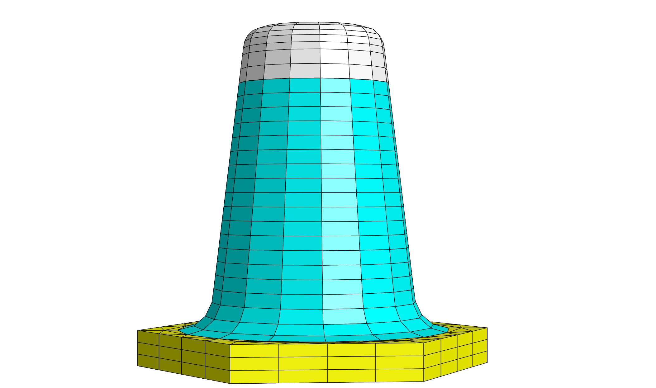
This example describes a unit cell of a hexagonal lattice (equilateral triangular lattice) of cones with capping layer and corner rounding. The computational domain is specified as an extruded polygon, the cone is specified as extruded circle where radius and material change with the z-coordinate.
In contrast to the scripting variant of this example we do not use Matlab® or Python but define the height dependence of the circles Radius as a piecewise defined polynomial. Here, the typical Radius=120 definition is replaced by a section Radius { ... } which yields a PiecewiseMonomial. At each Interface (enumerating the LayerInterface between subsequent layers we set a radius and JCMgeo uses a polynomial in between sampling points. In addition we have simpler CornerRounding syntax to describe a circular arc at the bottom and top of the structure. Note that JCMgeo detects the top/bottom facets of the cone as the layers where the Circle primitive is not mapped to the background material.
The following figure shows an image of parts of the geometry and mesh:
Input Files
layout.jcm [ASCII]
 1
 2
 3
 4
 5
 6
 7
 8
 9
10
11
12
13
14
15
16
17
18
19
20
21
22
23
24
25
26
27
28
29
30
31
32
33
34
35
36
37
38
39
40
41
42
43
44
45
46
47
48
49
50
51
52
53
54
55
56
57
58
59
60
61
62
63
64
65
66
67
68
69
70
71
72
73
74
75
76
77
78
79
80
81
82
Layout3D {
  Name = "TutorialExample3D"
  UnitOfLength = 1e-09
  MeshOptions {
    MaximumSideLength = 100
    MinimumMeshAngle = 20
    CurvilinearDegree = 2

  }
  BoundaryConditions {
    Boundary {
      Class = Periodic
      Direction = Horizontal
    }
    Boundary {
      Class = Transparent
      Direction = Vertical
    }
  }
  Extrusion {
    Objects {
      Polygon {
        Name = "ComputationalDomain/Air"
        DomainId = 101
        Priority = -1
        Points = [125.000 216.506 -125.000 216.506 -250.000 0.000 -125.000 -216.506 125.000 -216.506 250.000 -0.000]
      }
      Circle {
        DomainId = 102
        Radius {
          PiecewiseMonomial {
            AtInterface {
              Interface = 1
              Radius = 150
            }
            AtInterface {
              Interface = 2
              Radius = 107.025
            }
            AtInterface {
              Interface = 3
              Radius = 97.2026
            }
            CornerRounding {
              Top {
                Radius = 30
                Type = Convex
              }
              Bottom {
                Radius = 50
                NPoints = 4
                Type = Concave
              }
            } # CornerRounding
          }
        } # Radius
      }
    } # Objects
    MultiLayer {
      Layer {
        Thickness = 50
        DomainIdMapping = [101 1, 102 1]
      }
      Layer {
        Thickness = 350
        DomainIdMapping = [101 4, 102 2]
      }
      Layer {
        Thickness = 80
        MeshOptions {
          MaximumSideLengthZUpper = 5
          ProgressionZUpper = 3
        }
        DomainIdMapping = [101 4, 102 3]
      }
      Layer {
        Thickness = 40
        DomainIdMapping = [101 4, 102 4]
      }
    }
  }
}
Note
The concept of GeometryValues is conceptually similar but yields only a PiecewiseLinear height variation.
Note
The mesh parameters in the example may not be suitable for computation and will likely report strong deformations coarse meshes with curvilinear elements.