Mesh Options
Learning targets
- Define global and local mesh constraints
- Maximum side length of a mesh element (
MaximumSideLength) - Quality triangulation: Define the minimum angle of a mesh element
The mesh generator JCMgeo allows to define global and local mesh constraints.
It is possible to restrict the maximum side length of mesh elements, the maximum area
of mesh elements, and the minimum inner angle enclosed by edges of the mesh elements.
The following layout defines some global settings (MaximumSideLength = 2.0,
MinimumMeshAngle = 25.0) within the MeshOptions section which are valid for all objects in the layout unless
they are redefined for a specific object in the object definition.
Layout2D {

  MeshOptions {
    MaximumSideLength = 2.0
    MinimumMeshAngle = 25.0
  }
  Objects {
    Polygon {
      Name = "ComputationalDomain"
      ...
    }
    Circle {
      Name = "Circle_Left"
      ...
    }
    Circle {
      Name = "Circle_CenterLeft"
      MeshOptions {
        MaximumSideLength = 0.6
      }
      ...
    }
    Circle {
      Name = "Circle_Center"
      MeshOptions {
        MinimumMeshAngle = 30.0
      }
      ...
    }
    Circle {
      Name = "Circle_CenterRight"
      MeshOptions {
        MinimumMeshAngle = 3.0
      }
      ...
    }
    Circle {
      Name = "Circle_Right"
      RefineAll = 3
      MeshOptions {
        MinimumMeshAngle = 30.0
        MaximumSideLength = 0.6
      }
      ...
    }
    Polygon {
      Name = "ThinObjectTop"
      MeshOptions {
        MinimumMeshAngle = 2.0
      }
      ...
    }
    Polygon {
      Name = "ThinObjectBottom"
      ...
    }
  }
}
The layout contains five circles of identical dimensions (except for a global shift of the center position):
- The object
"Circle_Left"gets both constraints from the global settings for the layout. - The object
"Circle_CenterLeft"comes with a smallerMaximumSideLengthand thus is discretized with more mesh elements. - The object
"Circle_Center"has a more restrictiveMinimumMeshAngleand is also discretized with more mesh elements, compared to"Circle_Left". - The object
"Circle_CenterRight"has a smaller allowed minimum mesh angle which leads to a coarser triangulation. - The object
"Circle_Right"comes with restrictiveMinimumMeshAngleand smallMaximumSideLength. Further the finesse with which the circumference is discretized is higher (RefineAll = 3).
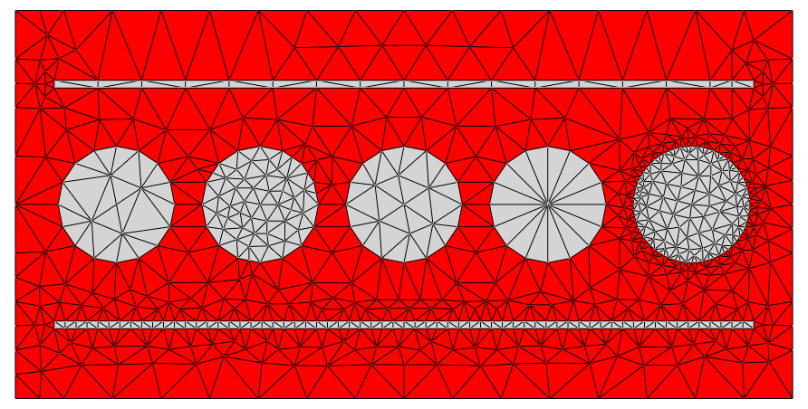
Further the layout contains two polygons with identical dimensions one of which has a lower constraint on the minimum mesh angle which leads in a drastic reduction of mesh elements used in this part of the triangulation.
Note
- The global and local fineness of the mesh, together with numerical parameters for the FEM solver, typically have great influence on numerical accuracy of the computed solutions.
- The total number of mesh elements, together with numerical parameters for the FEM solver, influences computation time and memory demands.
- The shape of mesh elements typically moderately influences numerical accuracy of the computed solutions (typically mesh elements without inner angles greater 90 degree have very good convergence properties).
Note
- The FEM solver
JCMsuiteallows for adaptive mesh refinement during the run-time of the solver. This allows to further automatically, locally refine the mesh obtained from the layout with the mesh generatorJCMgeo.