Cn Symmetric Problem
In this tutorial we exploit the discrete rotational symmetry of a multicore fiber structure to reduce the computational domain. The geometry exhibits  symmetry, allowing us to restrict the simulation to a single sector of the full device while still capturing the complete modal behavior.
 JCMsuite can expand the full geometry and field distribution by applying the specified rotational symmetry from the computational domain sector.
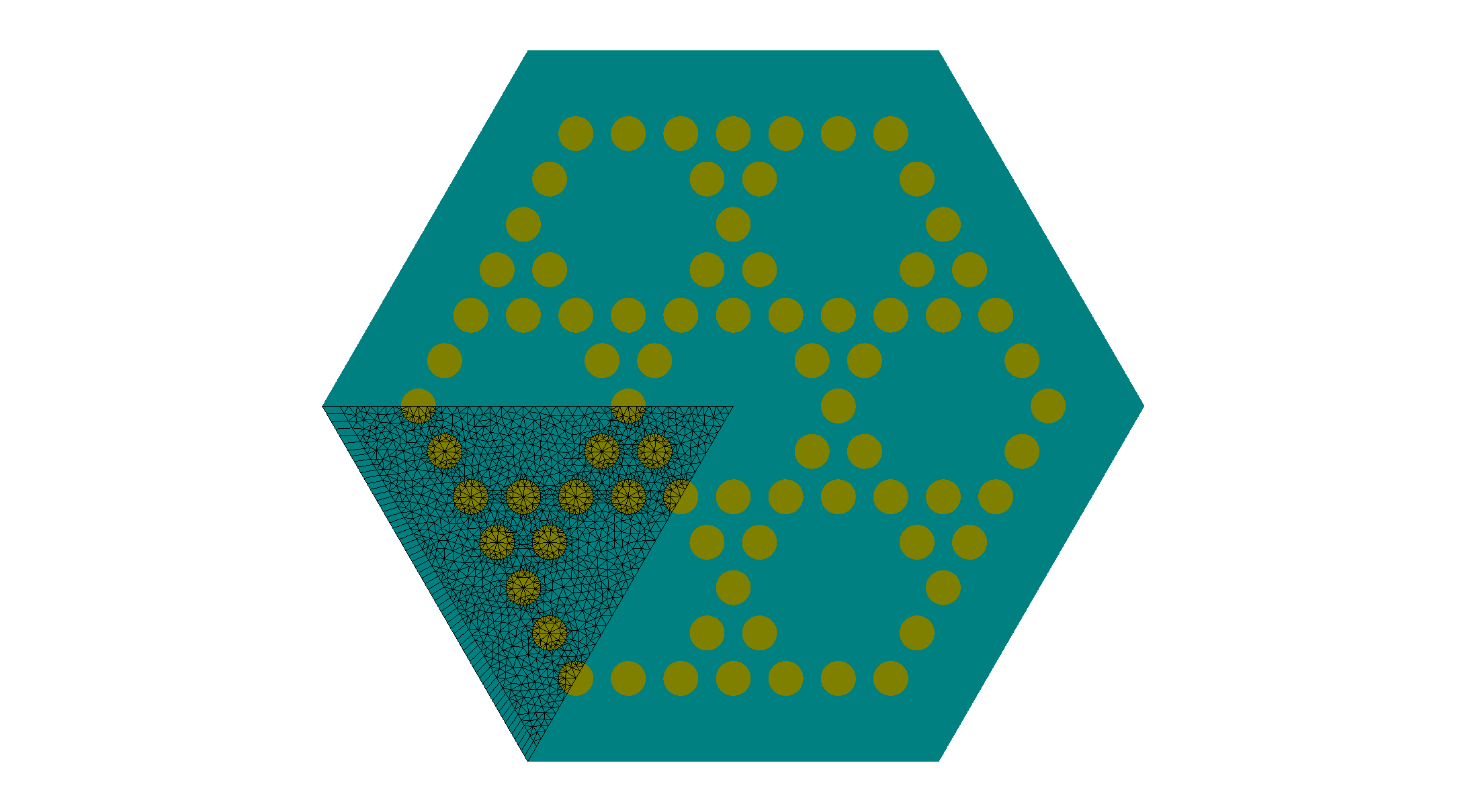
Geometry construction with cyclic symmetry
The computational domain is defined as a single triangular sector representing one symmetry leaf of the full structure. The sector angle corresponds to the rotational symmetry order of the device.
The reduction is achieved by assigning cyclic symmetry boundary conditions to the corresponding edges of the computational domain.
In the layout.jcm file the boundaries tagged with Class = Cn define the periodic interfaces across which the rotational symmetry is enforced.
7 8 9 10 11 12 13 14 15 16 17 18 19 20 21 22 | Triangle {
AngleAlpha = 60
AngleBeta = 60
DomainId = 2
Priority = ComputationalDomain
Width = 22.5
Port = Point1
RotationAngle = 180.
Boundary {
Class = Transparent
}
Boundary {
Number = [1 3]
Class = Cn
}
}
|
The multicore structure itself is generated using a lattice description. The positions of the individual cores are specified via LatticeCopies. The list of lattice positions is identical to the one used in the mirror-symmetry-reduced model. However, due to the cyclic symmetry reduction, only the cores located within the fundamental sector contribute explicitly to the mesh; the remaining cores are reconstructed automatically through symmetry operations.
Mode selection in multicore fibers
In contrast to mirror symmetry, cyclic symmetry introduces a phase shift between adjacent sectors. This phase relation is controlled by the parameter NCyclicSymmetry, which defines the symmetry index of the mode. In this example we compute the two fundamental symmetric solutions close to a refractive index guess by setting:
SelectionCriterion {
  NCyclicSymmetry = 0
  NearGuess {
    Guess = 1.448
    NumberEigenvalues = 2
  }
 }
Higher-order angular mode families can be accessed by choosing non-zero values of NCyclicSymmetry. In the subfolder data_analysis you’ll find a more intricate example scanning and superimposing the different symmetry modes to find modes confined to single cores.
For multicore fibers, the eigenvalue problem typically yields a large number of modes, many of which are not physically relevant for the desired application. To isolate the guided modes localized in the fiber cores, we apply an additional filtering strategy.
This ensures that only modes with significant field overlap in the cores are selected, we define a spatial filter based on the confinement factor. This requires specifying regions that correspond to the individual fiber cores:
Filter {
  ConfinementFactor = 0.1
  CoreRegion {
    Ellipsoid { ... }
    Ellipsoid { ... }
    ...
  }
}
The ellipsoidal regions mark the positions of the cores in the multicore fiber. Only modes with sufficient energy concentration inside these regions are retained. This step is usefull to suppress cladding or leaky modes and to reliably extract the physically relevant guided modes.
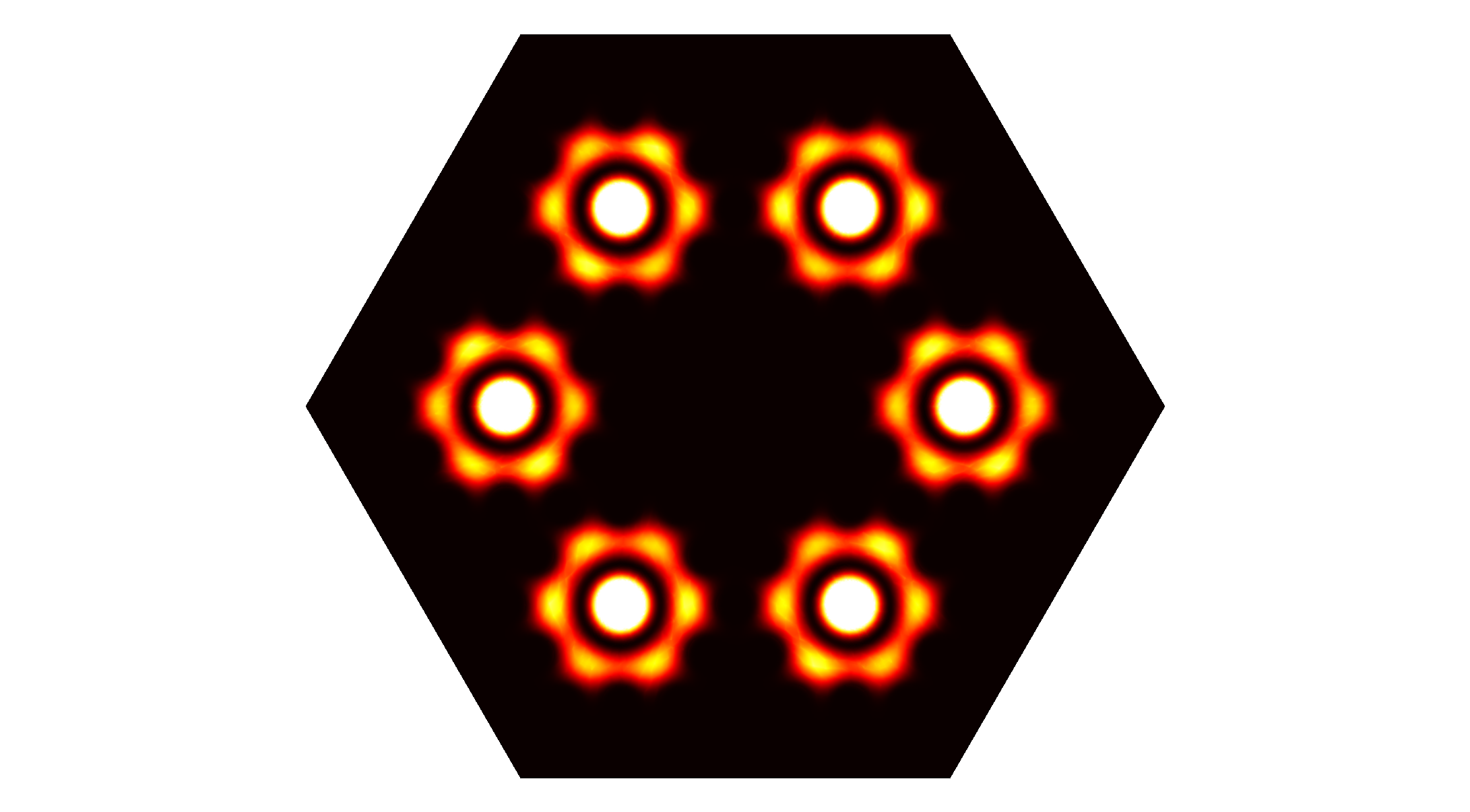
Visualization of results
After solving the eigenvalue problem, JCMview can be used to visualize the full reconstructed field distribution. Both intensity and vector plots are expanded to the complete fiber cross section.
 |
 |
The resulting field patterns clearly show the modal distribution across all cores of the fiber. For NCyclicSymmetry = 0 the intensity distributions look identical in each sector, corresponding to a fully symmetric supermode. However the vectorial plot reveals the cyclic nature in the orientation of the electric field vectors of the mode