Hollow Core
The JCMsuite layout description offers a number of ways, to set up complex geometries.
E.g., in the Multi Core example we use lattice copies to create the arrangement of air pores of a solid core photonic crystal fiber.
For some applications it might however be necessary to describe geometries, which can not be represented by simple primitives as circles, parallelograms, etc. or where the complex arrangement of similar objects is not bound to a regular grid, needed for lattice copies.
In such cases it is often required to describe geometrical objects by arbitrary boundary curves, i.e., generic polygons.
This is the case for the present example, where the inner pores of the photonic crystal cladding and the central pore form complex shapes.
The description of a polygon defining a single pore in the layout file is shown in the following:
 Polygon {
  Name = "Polygon_1"
  DomainId = 2
  Points = [2112 705.6374990036 2185.3202328111 622.0317970206 2285.0538122243 572.8486385112 2396.0172048613 565.575713512 2501.3172400786 601.320258925 2841.9 797.955807047 2900.9254326382 843.2476144874 2946.2172400786 902.2730471255 2974.6888604924 971.0096192713 2984.4 1044.7730471255 2984.4 1558.4993166505 2974.6888604924 1632.2627445047 2946.2172400786 1700.9993166505 2900.9254326382 1760.0247492886 2841.9 1805.316556729 2397 2062.1796914915 2328.2634278542 2090.6513119053 2254.5 2100.3624514129 2180.7365721458 2090.6513119053 2112 2062.1796914915 1771.4172400786 1865.5441433695 1687.8115380956 1792.2239105584 1638.6283795862 1692.4903311452 1631.355454587 1581.5269385082 1667.1 1476.226903291 ]
}
Clearly this description can hardly be done “by hand”, entering coordinates of all points.
Instead, setting up a complex geometry and the simulation run is done with the help of JCMsuite’s Matlab® Interface.
The geometrical setup is a hollow core photonic crystal fiber as depicted below:
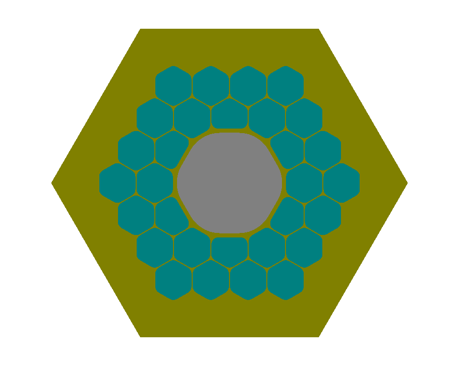
JCMsuite’s Matlab® Interface allows generation of such complex files using so called template files.
Thereby JCMsuite syntax and Matlab syntax can be mixed, e.g., to compute the point locations of the pores.
Matlab loops allow generation of multiple objects at displaced positions or modified shapes.
A complete description of the mechanism can be found in the Matlab® Interface
and is beyond the scope of the present example, which merely serves as a demonstration of the capabilities of embedded scripting.
This example includes template files for project.jcmp, layout.jcm, and materials.jcm where a “t” is added as suffix for the corresponding templates.
The templates are designed in such a way that only a few user defined parameters, as corner rounding, periodicity, number of cladding rings, etc. have to be defined to generate the complex layout description.
These main input parameters are set in the run_project.m script.
When it is executed in Matlab, the command:
results = jcmwave_solve('project.jcmp', keys);
within the run_project.m script converts the templates into regular JCMsuite input files, meshes the layout, and runs the simulation.
Further, the scripts writes the eigenvalues, stored in the results struct into the console.
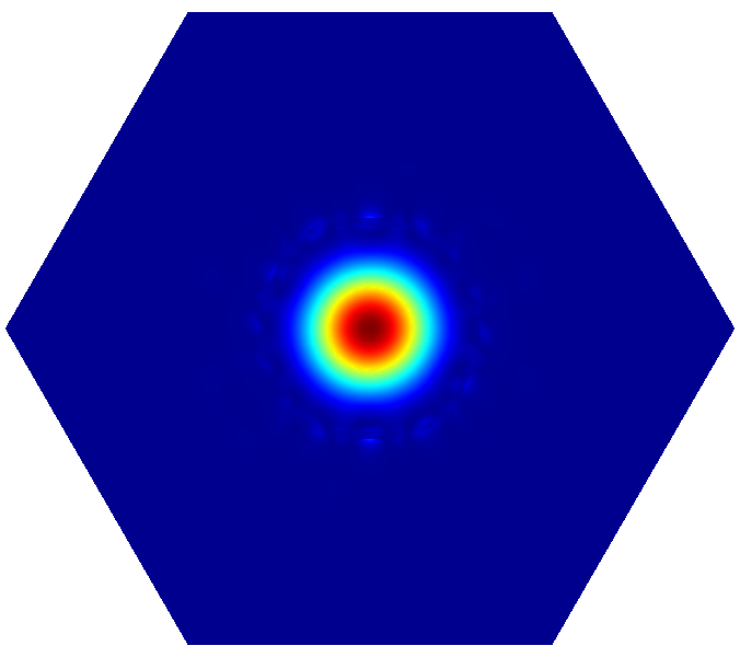
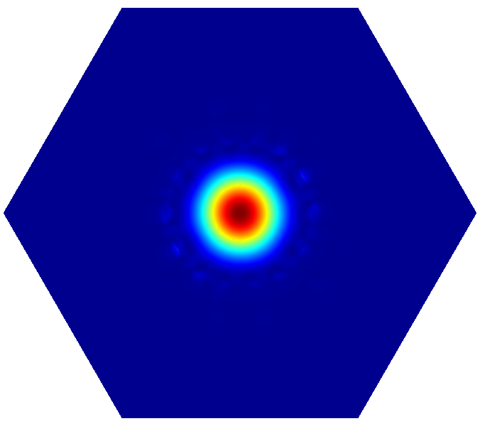
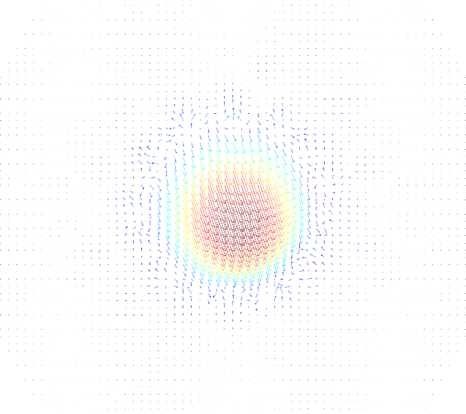
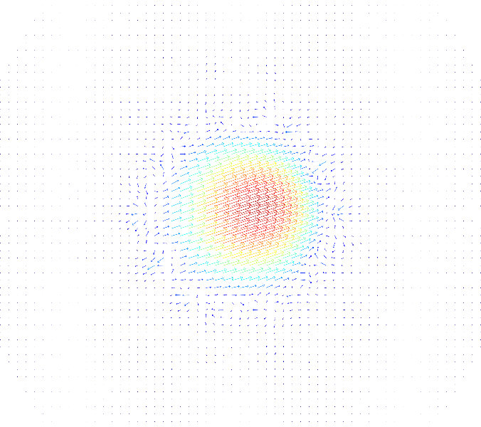
The computed hollow core mode is two-fold degenerate. The following figure shows the computed intensities of the modes (upper row) and the corresponding vector fields (lower row).
 |
 |
 |
 |